DIY aquarium doser using a Raspberry Pi
Taking a sledgehammer to crack a nut
11. Dec. 2019
Why fertilize?
Fertilization is essential for a heavily planted and illuminated aquarium. Especially when there are few animals in it oftentimes there's too little organic waste that can be used by the plants.
A daily fertilization is optimal compared to a weekly fertilization, but thanks to my forgetfulness I often failed to stick to a proper schedule. This creates a nutrient imbalance in the aquarium which hinders plant growth while promoting algae growth. The solution: Automating the process. The problem: It's expensive. Therefore: Let's DIY.
For now, the doser shall dose an iron fertilizer and a macro fertilizer. In addition there should be an extra channel for a fertilizer that I may want to fertilize later. Three pumps must therefore be controlled.
A Raspberry Pi which is currently lying around here having no use is to be used to control the dosing pumps. The Raspberry Pi including a power supply and a SD card costs around € 50. This solution represents a quick and dirty interim solution until my DIY aquarium controller is finished. The control with the Raspberry Pi is rather something for those who either have a Raspberry Pi left or the Raspberry Pi want to expand further to control the aquarium. Obviously the Pi and its full fledged Linux as an operating system is somewhat oversized to switch two pins once a day.
Hardware
The Raspberry Pi cannot drive the pumps directly. It can provide a maximum of 3 mA at 3.3 V per channel. Therefore a small circuit switching the pumps via transistors and relays has to be created.
Three eBay metering pumps are used as hardware. Each for about 15 € to be removed from a small electrical device as described in the description means so beautiful. A little plywood, screws for a "housing" and a little electronics. Here is the component list in detail:
| Quantity | Product | Source | Total |
|---|---|---|---|
| 3 | Dosing pumps | Ebay | 50 € |
| 3 | Plywood 12 mm x 240 mm x 85 mm | Baumarkt | 2 € |
| 1 | Plywood 12 mm x 240 mm x 350 mm | Baumarkt | 2 € |
| 1 | Raspberry Pi incl. power supply and SD-card | z.B. Reichelt | ~ 50 € |
| 3 | Relais Finder FIN 36.11 5V | Reichelt | 3 € |
| 1 | Power supply 9 V | Reichelt | 7,50 € |
| 3 | Transistor BC548A | Reichelt | 0,15 € |
| - | Cables, Resistors (4,7 kΩ), Diodes | Reichelt, Own stock | - |
| 1 | CO2 tube 2,5 m | Hardware stor | 2,70 € |
| Sum | ~ 117,35 € | ||
Assembly
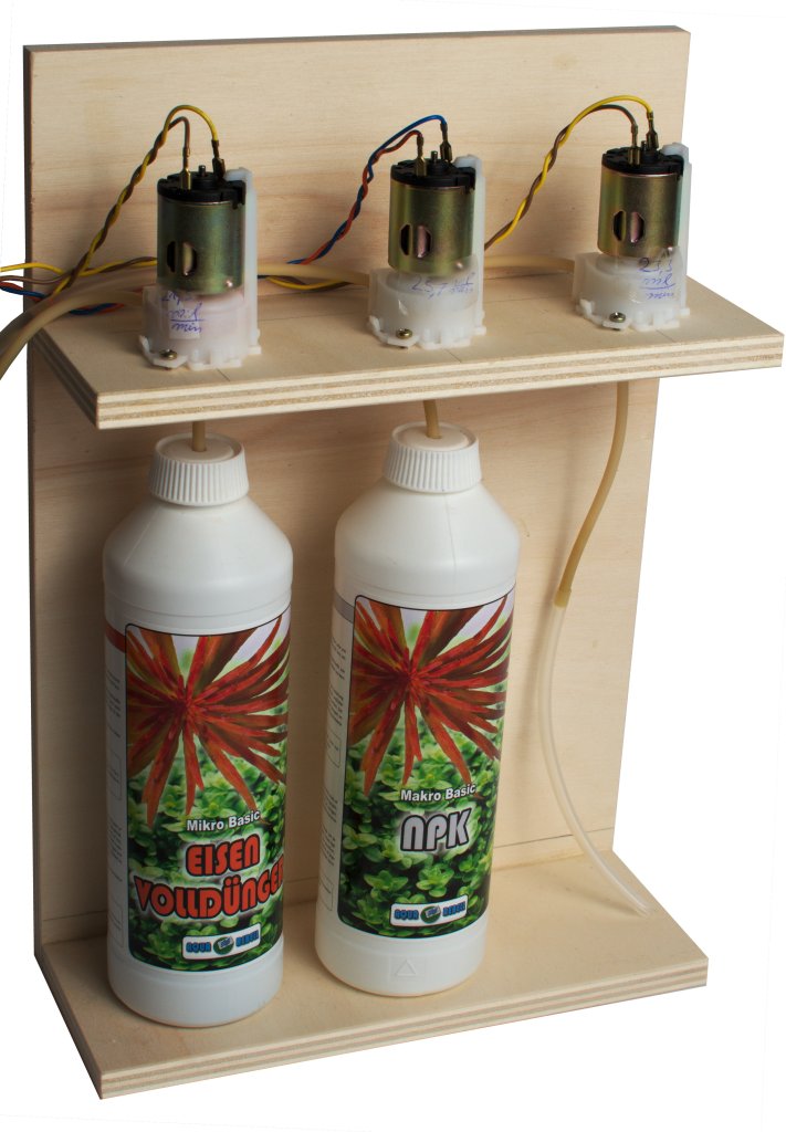
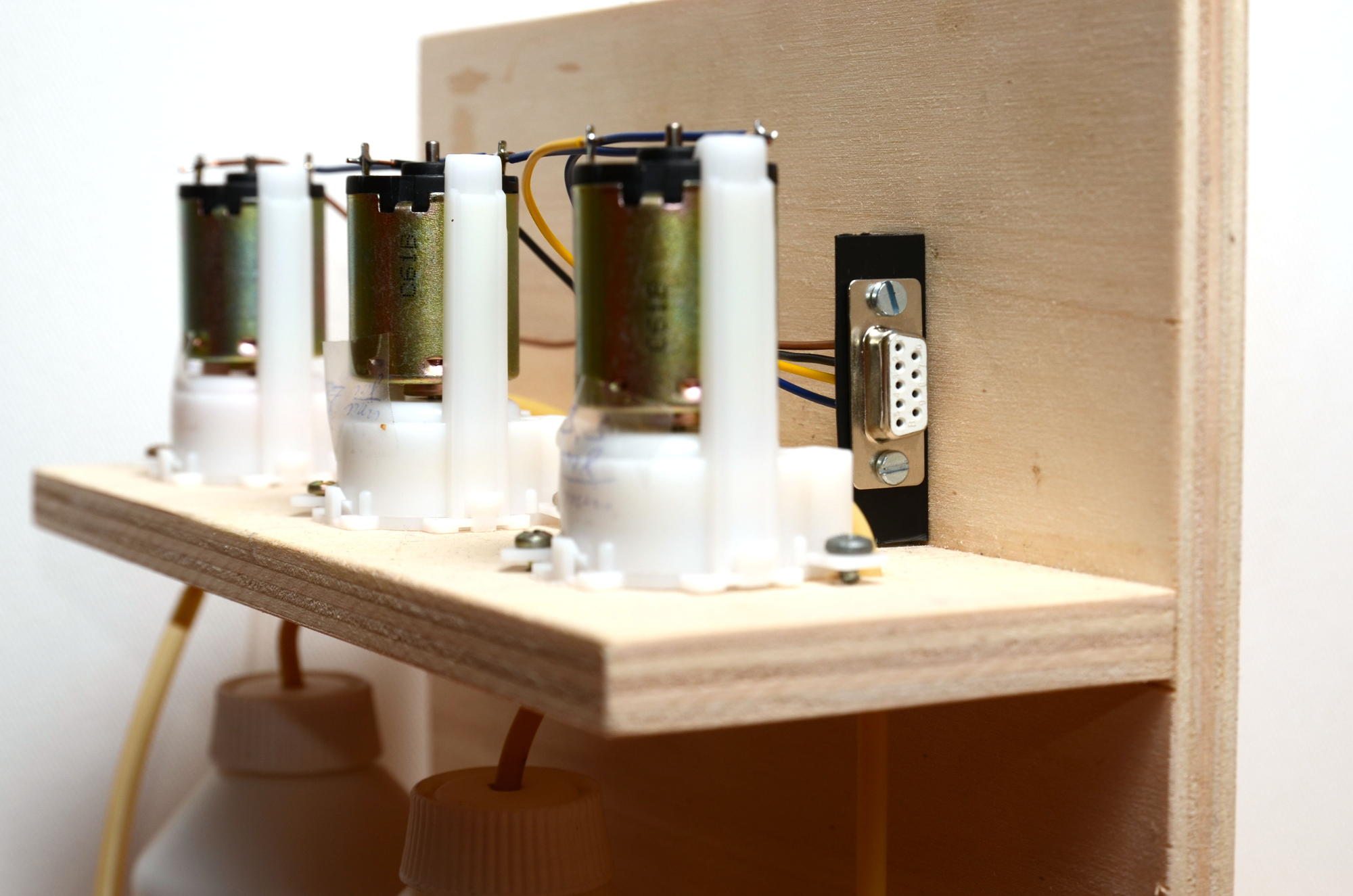
Bottle holder and pumps
My build is based on this dosing system of a user of flowgrow.de. It consists of a base plate on which the 500 ml fertilizer bottles are placed, another plate above the base plate with large holes in which the Bottles stand to ensure a secure stand (due to the lack of a hole saw this is not yet implemented), a plate to which the pumps are attached and one back wall to which everything is attached. The plates are held together with two screws each and some glue.
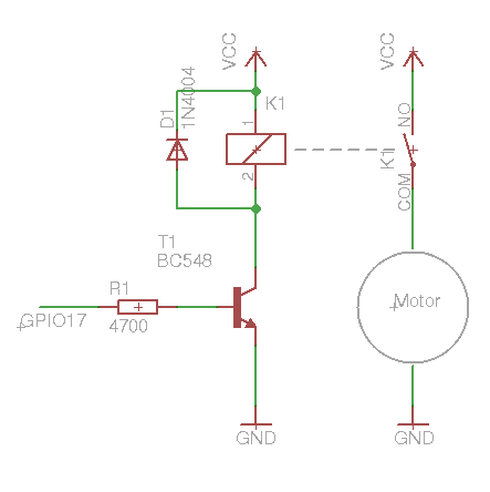
Relais board
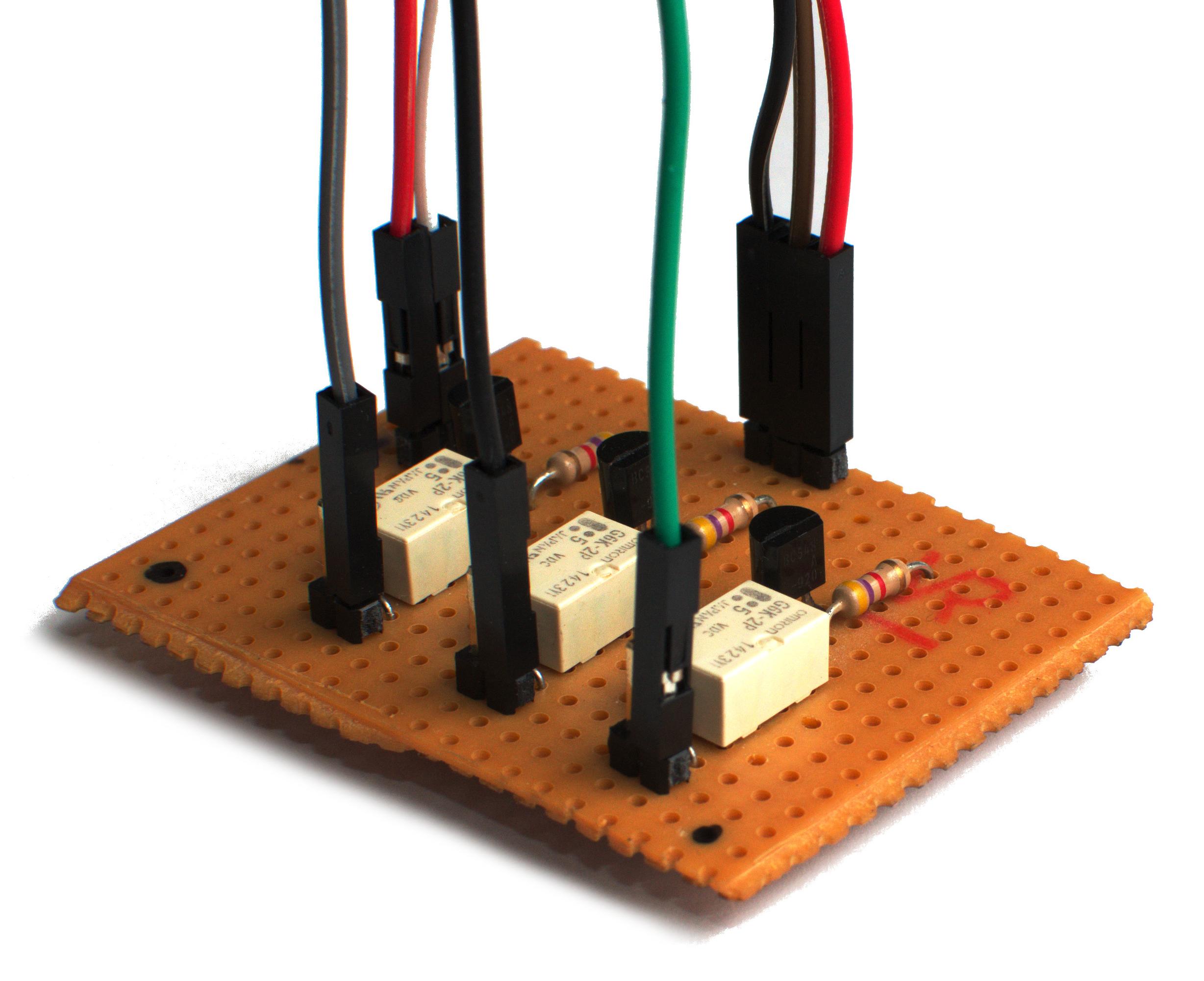
A relay board was designed to switch the pumps with the GPIO outputs of the Raspberri Pi. The Raspberry Pi delivers a maximum of 3 mA at its outputs, which is not enough to swithc the relays. A transistor is therefore required to switch the higher current the relays need. A diode in parallel to the relay reduces the reverse voltage spike that occurs when the coil is switched off. Below is the circuit diagram I came up with.
Determining the flowrate
In order to be able to fertilize the desired amount of fertilizer later, the flowrate of the Pumps has to be determined. For this I have the pumps running individually 10 minutes each pumping water to an empty container. I determined the amount by pumping out the vessel with a 5 ml syringe. Using an accurate kitchen scale or an accurate measuring cup would be less annoying here.
Software
The software that controls the pumps is nothing more than a simple Bash script
(see below). In the fertilize array, "on-times" are given in seconds for the
respective channel. Following are the initialization functions for the GPIO pins
of the Raspberry Pi. The actual Program sequence follows at the end of the file.
First the initialization function is called, then the individual fertilizer channels
are switched on and off one after the other. The script is called by
CRON at any time.
For me, the entry in the crontab for daily fertilization at 10 a.m. looks like this:
0 10 * * * /bin/bash /root/fertilize.sh
The crontab can usualle be edited with crontab -e. Don't forget: The script
must be executable, otherwise nothing will happen!
You can do this with chmod + x fertilize.sh
This is the complete script:
##!/bin/bash

fertilize[0]=2.8 # 1 ml
fertilize[1]=1.2 # 0.5 ml
fertilize[2]=0

function init {
    if [ ! -f /sys/class/gpio/gpio17/direction ]
    then
        echo "17" > /sys/class/gpio/export
        echo "out" > /sys/class/gpio/gpio17/direction
    fi

    if [ ! -f /sys/class/gpio/gpio22/direction ]
    then
        echo "22" > /sys/class/gpio/export
        echo "out" > /sys/class/gpio/gpio22/direction
    fi

    if [ ! -f /sys/class/gpio/gpio23/direction ]
    then
        echo "23" > /sys/class/gpio/export
        echo "out" > /sys/class/gpio/gpio23/direction
    fi
}

function relais1_on
{
    echo "1" > /sys/class/gpio/gpio17/value
}

function relais1_off {
    echo "0" > /sys/class/gpio/gpio17/value
}

function relais2_on {
    echo "1" > /sys/class/gpio/gpio22/value
}

function relais2_off {
    echo "0" > /sys/class/gpio/gpio22/value
}

function relais3_on {
    echo "1" > /sys/class/gpio/gpio23/value
}

function relais3_off {
    echo "0" > /sys/class/gpio/gpio23/value
}

init
relais1_on
sleep ${fertilize[0]}
relais1_off
sleep 0.2
relais2_on
sleep ${fertilize[1]}
relais2_off
sleep 0.2
relais3_on
sleep ${fertilize[2]}
relais3_off